



 Fulvio Chiappetta
The goal I set myself with this article is as seemingly simple as it is basically ambitious: I will in fact try to explain, at an extremely popularized level, the principle on which the operation of switching amplifiers is based.
The A B C of switching amplification.
I have also written this article for those with modest knowledge of electrical engineering and electronics (those strictly necessary will be mentioned in the course of the discussion) and will explain-or at least try to explain-the working principle of switching amplifications. I will use simplifications while trying to be as clear as possible. I believe it is important to deal systematically and comprehensively with the subject, starting with the basics, since quite often audiophiles and DIYers speak with apparent knowledge of switching amplifications, also referred to equivalently as switching amplifications (Class D, Class T, Cold Class and more) when in fact it is not very clear. In fact, I often realize that the vast majority confuse about these technologies since the operating principle of switching amplifications is quite different and really has nothing to do with that of similar traditional type realizations which, with correct language, should be called linear type.
How does a switching amplifier work?
In my opinion, the easiest way to explain this is to make a whole series of observations, at least initially, in a different realm than sound. The possible ways of lighting a light bulb for example. We shall see in a moment why this is so and how far the dictates, derived from the considerations that will follow it, can be an effective premise for understanding the operation in the sonic domain of switching amplifications. Let us refer to what is illustrated in Fig.1:

we have a simple circuit, similar to what we daily face in our daily experience and therefore we should be used to it and nothing should be new or difficult to us. The switch placed in series with the circuit that connects the bulb with the source of energy, which in our exemplification is a battery, but which could easily be the 230V of the electrical outlet, when it is open, as shown in the figure, does not allow the passage of electric current to the bulb, which will therefore be turned off. Let us now consider what happens in Fig.2

The whole thing is similar to what is shown in the previous picture, the only difference being that the switch is closed and consequently there is current flowing to the bulb, which therefore turns on. Premised on these very simple considerations, suppose we want to turn on the bulb at a different brightness value than the maximum, just to fix ideas equal to half. Fig.3 shows us what we could do: in place of the switch we could place an electrical component that is called a resistor, which, as the word itself says, opposes a certain resistance to the passage of current, which, being reduced by it, lights the bulb at an intensity that is share part of the maximum. It is evident that, by properly calibrating the bottleneck to the passage of current operated by the resistor, it is possible to obtain the desired result: to light the bulb at an intensity equal to half of that previously obtained in Fig.2, which is obviously to be considered the maximum, operating with the power source at our disposal. In fact, referring again to what happens in Fig.2, the switch, being on, closes the circuit and allows a full flow of current from the power source, in this case the battery, to the user, in this case the bulb. Let us now return to a close examination of what happens in Fig.3:

Thanks to the introduction of the resistor, we have achieved the goal of lighting the bulb at a lower intensity than the maximum intensity, but at what cost? A part of the voltage supplied by the battery falls at the ends of the resistor and at the same time the current that powers the bulb flows in it: the product of this voltage drop multiplied by the intensity of the circulating current determines the power dissipated in the resistor. This simple notion of electrical engineering is indispensable for full enjoyment of the concepts we are expounding: when, in an electrical component, a current is simultaneously circulating and a voltage drop is consequently determined at its ends, the product of I (the current) by V (the voltage) determines energy dissipation, in other words, the component heats up. We also perform what is, with obvious meaning of the term, referred to in the jargon as energy balance; referring again to Fig.3, the battery not only gives the energy deputed to the lighting of the bulb, but also that dissipated in the resistor: in other words, a part of the power delivered by the battery is dissipated, i.e. lost, in the resistor and the efficiency of the system, considered as the ratio between the energy supplied by the battery and that used by the bulb, which is the one that really interests us (that dissipated in the resistor is unfortunately only wasted power) is certainly not equal to unity, or reported on another scale, equal to 100%. In order to avoid what I would not hesitate to call a real energy waste, let us look for a viable alternative to the previously adopted brightness reduction technique. Let us refer for clarity to what is depicted in Fig.4:

Suppose, thanks to an appropriate cadence of closing and opening the switch inserted in the circuit, we turn the bulb on and off at regular intervals, somewhat like the direction arrows on a car. In our exemplification, the time during which the bulb is off is absolutely equal to the time during which it is on: what happens? The average value of brightness is obviously half that obtained by constantly turning the bulb on; moreover, provided of course that the frequency with which the repeated alternations occur is sufficiently rapid, to our eyes, thanks to the well-known phenomenon of the persistence of the image on the retina, the bulb will not appear to turn on and off, but rather will appear to shine at an intensity equal to half the maximum intensity it exhibits in the case of Fig.2. Suppose now that we want to light the bulb at a different intensity, for example, one quarter of the maximum intensity; still following the same procedure, let us assume that we divide the unit of time into four parts and keep the bulb lit only in the first quarter, as shown in Fig.5 for clarity:

In this case the average value of the luminous intensity will be equal to the quarter of the maximum one, as sought. Even in such a situation, provided of course that we keep sufficiently high the rate at which we alternate the periods of turning the bulb on and off, the brightness of the bulb will appear to our eyes to be constant and precisely equal to one-fourth of that in Fig.2. Finally, suppose we want to light the bulb at an intensity equal to three-fourths of its maximum intensity; we deem it unnecessary to dwell in further explanation, but merely report in Fig.6 what must appropriately take place.

This is the result we wanted to obtain and on which we now conduct an important series of observations. First, we believe that we have shown that it is possible to obtain with simplicity, exclusively by varying, within the unit of time, the percentage of light bulb on and the percentage of light bulb off, any intermediate brightness of the bulb. This is of great importance if one takes into account the fact that, unlike using the current intensity-damping resistor, in this case there is no energy expenditure: the variation in intensity is due only to the alternation, appropriately sized in time, of two phases, in each of which there is no power dissipation. In fact, in one case, the bulb is fully on and this corresponds to a closed switch, and in the other the same is totally off and corresponds to an open switch: in the first occurrence there is no voltage drop at the ends of the switch, while the circulation of current is maximum; in the second, there is no current passing through it, while the potential drop at its ends is maximum, since it is equal to that of the battery; since, as we had stated above there is power dissipation only if at the same time voltage drop and current are different from zero, in the switch, by its very constitution, there is never power dissipation. It is evident that in practice, in order for the whole thing to work properly, there is certainly no frantically activated mechanical switch, but rather a suitable electronic component that, driven by an appropriate circuit, behaves in the same way as the mechanical switch: there is more than one solid-state electronic component that, within the range of frequencies of switching that are not very high, can approximate very well the operation of a practically perfect switch. Second, building on the synthesis of the considerations made thus far, we certainly have an additional element of very great importance to which to draw our attention: we have asserted that it is possible for the eye to see the bulb not turn on hiccup-like, but rather continuously at an intensity equal to the average value of the energy administered to it over time, thanks to the eye’s ability to integrate the information that has succeeded one another over time, operating in the specialty of our case, for them an average; in other words, the eye acts as a filter that eliminates the most rapid variations in light intensity. For the filtering action to be effective, however, the phenomenon must take place with appropriate speed; in case the latter is insufficient, we could, as previously mentioned, distinctly perceive the succession of onsets and offsets, and then, as the frequency with which they alternate, highlighting a flicker that is very tiring to our vision and only for a sufficiently rapid succession of phenomena, finally seeing the light as fixed.
Let's transfer these concepts to the field of audio

On the strength of what we have previously experimented with, let us try to transfer this to the audio field.Let us reproduce in Fig.7 the functional diagram of an amplifier for audio frequency: as can be seen immediately it can be seen as the chain formed by an actuator which, receiving at its input the signal to be amplified, with its output controls a variable resistor thanks to which a current circulates, instant by instant, in the loudspeaker such that the cone of the latter can move according to an appropriate sequence, obviously correlated to the signal input to the amplifier. Certainly in the reality of practical implementation there are no variable resistors, but transistors or power tubes are functionally nothing more than resistors that vary their value because of an appropriate control signal. It is immediate to observe that what is illustrated in the right-hand side of Fig.7 is not conceptually dissimilar to what we have shown in Fig.3, when we set ourselves the problem of turning on the light bulb, with brightness varying at will: in both cases the presence of the resistor that partializes the intensity of the current to be transferred to the user, in one case the bulb, in the other the loudspeaker, causes a considerable loss of efficiency for the reasons we have previously pointed out. Let us therefore assume that in the case of the audio amplifier, too, we implement a process similar to that followed for lighting the light bulb without energy loss: the circuit in Fig.7 is therefore transformed into that in Fig.8
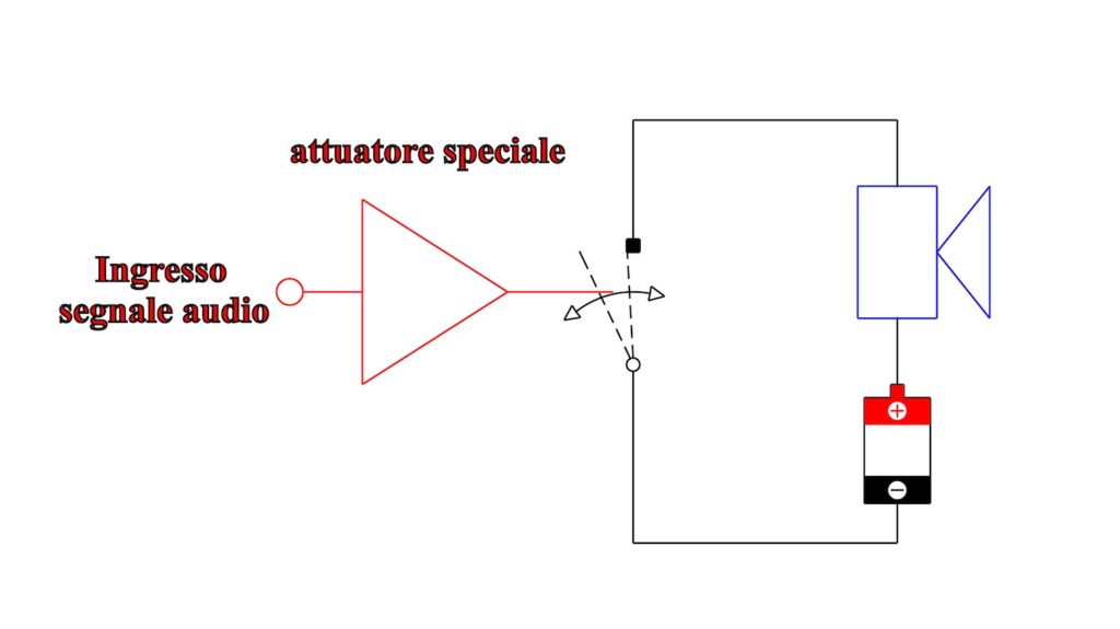
where there is always an actuator, but quite different from the one previously employed. It must now, with appropriate cadence, turn on and off the switch placed in series with the loudspeaker, so that the latter receives a signal whose average value is correlated, instant by instant, with that which is placed at the input of the amplification system. In this case, therefore, similarly to what we did in the case of the light bulb, we implement a modulation of the signal by operating not directly on the intensity of the current, but on the alternation of the times during which it circulates: the intensity of the current is always the maximum one, but it is the time during which it circulates that is controlled, as we saw earlier, according to an appropriate timing logic. All the observations about the unitary efficiency of the system, which we made when we set out the operating modes of the light bulb, also apply in this case, and therefore the circuit of Fig.8 can be to all intents and purposes, except for a not at all negligible detail which we shall point out shortly, that of a switching amplifier, characterized, as the name suggests, by the presence of a switch on the output, deputed to control the speaker. In the switch there is no energy dissipation and therefore the efficiency, at least in theory, of such types of systems is equal to unity: to obtain, for example, 100W in output, 100W are needed taken from the source, be it a battery or rather the light network, appropriately manipulated; nothing is dissipated, the amplifier does not heat up and can be extremely compact thanks to the absence of cooling fins. We have mentioned that the circuit in Fig.8 is still missing one piece, which is very important: in the previous paragraph, we highlighted the essential integrating function performed by the eye, which acts as a filter against rapid variations in intensity, allowing us to see the bulb as being lit steadily and not hiccupingly. Similarly, therefore, in order to prevent the loudspeaker from prancing along, driven by the pulses and not by their mean value, which, let us remember, is the only one really related to the input signal to the amplifier, it is essential to add an appropriate filter stage to the schematic shown in Fig.8; we thus arrive at the block circuitry shown in Fig.9, which can be considered, to all intents and purposes, the final and functionally complete circuitry of a switching amplifier. Since the filter stage we have added is essentially the weak point of switching amplifiers, we devote the next section to it.

The output filter
The difficulty in realizing this filter will be immediately apparent given the two main characteristics it must have:
- it must perform effective integrating action with respect to the signal coming from the interrupter by returning to the speaker only the average value of the impulsive signal coming from the switch;
- it must not perform any integrating action vis-à-vis the audio signal: if it did, the most rapid temporal variations would be lost.
Arduous task ! Indeed, its intervention must be extremely effective against certain signal variations harmful to good listening, and instead ineffective, or better yet transparent, against certain others. In Fig.10 we have highlighted what we expect from the filter: all signals with a frequency of at least 20,000Hz must pass unaltered through its meshes, while those related to the frequency (or frequencies, since it is not always, especially in the most refined realizations, fixed) of switch switching must be completely trapped in them. In order for things to unfold optimally there are evidently two ways forward: either the switching frequency is raised so as to be much higher than 20,000Hz, say at least by a few orders of magnitude, or the slope of the filter (i.e., the behavior at immediately successive frequencies) must be very high, in order to discriminate effectively between desired and unwanted signals.


Figs. 10 and 11 show these two possibilities for clarity, respectively. Let us say at once that the second one, the one implemented with a filter characterized by great rapidity of attenuation, is very impractical; in fact, since the filter unit is directly interfaced with the load constituted by the loudspeaker, an overly complex realization of it, which is indispensable for the achievement of a high slope, would penalize the sonic quality for reasons that we reserve the right to examine in further detail. We limit ourselves here to pointing out that this depends on the fact that the loudspeaker system is characterized by an impedance that is not only highly variable with frequency, but also not known a priori; moreover, it would be very limiting of the versatility of the amplifier to deliberately restrict its proper operation to very specific ranges of load values. All that remains, therefore, is to increase the switching frequency as much as possible, something, at the present state of the art, is becoming feasible, since with the latest realizations we have touched 2 Mhz, then millions of cycles, and in the future we may exceed 5 Mhz, arriving at a switching frequency even higher than ten times the maximum frequency of the signal to be amplified, bringing switching amplification now very close to that of the traditional type. The techniques mentioned above, although they could be of not excessively onerous implementation in terms of components and difficulty of realization, are generally proprietary and present only on boards available on the market already totally assembled, characterized by costs now not even too demanding, so much so as to find them on board of even relatively low-cost products.
The use of feedback in switching amplifications.
It is well known that counterreaction makes it possible to reduce the nonlinearities of an amplifier. The way in which counterreaction operates should be clear to our readers and followers, here, however, at the risk of being long-winded, we do not want to take anything for granted, and consequently we very briefly mention its principle of operation. The output signal to the amplifier should be equal to the input signal minus a multiplication factor equal to the gain of the amplifier itself. In other words instant by instant the output should be worth G times the input, where by G we have precisely indicated the gain, also called the amplification factor, as illustrated in the following formula:
Vout = G x Vin
where, with obvious significance of the adopted symbology, Vout and Vin are the voltage of the output signal and that of the input signal, respectively, while with G we have indicated the amplification factor of block “A.” Unfortunately, due to the inevitable nonlinearities, referred to in the audio industry by the generic term of distortion, imperfect is the equality between the first and second members of the above formula: to remedy this, the counter-reaction takes charge of comparing the actual output (certainly distorted) with the theoretical one (ideally free of distortion) and, starting from the analysis of the differences between the two, tries to correct the output signal in real time, in order to make it as close as possible to the desired one. In order to clarify the concept of feedback as much as possible, we give, at the bottom, an example, borrowed from a completely different field: we invite the less experienced to read it, preparatory to understanding the following. We know very well that where the use of counterreaction is reckless, there is no improvement in the sonic performance of the amplifier at all, far from it, so much so that often the best solution is to dispense with counterreaction altogether; but when, as in the case of switching amplifications, the system, in the present state of the art, can begin to be considered satisfactorily linear, with a quantitatively judicious use of counterreaction. To act properly, the feedback must correct the distorted output signal, necessarily in real time: this is quite easily achieved in traditional amplifications, but not in switching amplifications, in which the various signal manipulations, of indispensable implementation in such realizations, inevitably involve some delay between cause and effect. Some particular and ingenious techniques have recently made it possible to overcome this limitation: this has made possible the use of counterreaction, which if, and let us reiterate, only if, it is wisely dosed, allows real improvements in performance, not only those exhibited at measurements, but also and above all those related to behavior in the listening room. In current realizations, the counterreaction loop incorporates not only the actual amplifier section, but also the output filter: this also makes it possible to overcome to a large extent the limitation of use of switching amplifications resulting from the need to filter their output. As we were able to point out in the section devoted to it, the filtering of the signal in the systems considered here is always very critical and inevitably involves a strongly dependent frequency response trend, especially at the highest frequencies of the audio range, by the subject and phase of the load impedance offered by the loudspeaker; being able to incorporate in the counterreaction loop also the output filter and thus correct the inevitable nonlinearities attributable to it, makes it possible to strongly contain the dependence examined before; again, such results are mainly the prerogative of the best and most carefully designed realizations. In this regard, we emphasize that even if two apparatuses use amplification boards of similar type, coming for example from a third loose-parts manufacturer, the overall performance is not necessarily superimposable: often the context in which the board is used almost matters more than the board itself. A striking example of this can be found in the flagship amplifiers of some major manufacturers: for example, devices that make use of the cascaded multi-stage stabilized power supply achieve performance unknown to products that are only seemingly equivalent. To convince oneself of the extent to which the peripheral circuitry to a component makes a difference, one need only reflect on the fact that, for example in the case of digital players, the adoption of the same integrated amplifier in charge of conversion does not at all entitle one to consider the performance offered by the various machines it equips to be superimposable.
Amplification switching yesterday, today and tomorrow
From an examination of the past and its comparison with the present, we can assert that switching amplification has now earned a respectable place in high fidelity and even in the high end in a few rare cases. The fundamental improvements over the first timid realizations are eminently in two directions: a raising of the switching frequency and a broadening of the use of feedback. We invite, in this regard, to consult, as a summary synoptic picture, Fig.12. Obviously, we remain at the window, ready to resume the discussion of the subject when we catch sight of significant innovations on the horizon that are really worth talking about.





GIPHY App Key not set. Please check settings